Original-article audit
What this source can support
Reviewed 15 August 2026 · geometry completeness 65/100 · medium-low
status: linked child-component model present | dossier_url: https://www.bunkerstrategy.xyz/intelligence/countries/Sweden/fortifications/se-f9-save-new-berghangar-fuel | method: Hybrid Analog / Hybrid quantity model | base_sek_2026_ex_vat: 132993840 | range_sek_2026_ex_vat: low: 44978700 | high: 416454100 | model_confidence: Low | basis: Uses the exact 1,200 m³ storage capacity, one horseshoe portal system and proxy assumptions of 800 m² / 8,611 ft², 4,800 m³ excavation, 320 m³ concrete plus modern process/fire/protection packages. | assessment: The morphology, tank volume, single entrance system and child scope are sound. The 800 m² / 8,611 ft²/4,800 m³/320 m³ quantities are not published. The broad range appropriately reflects this, and the model already recognizes modern hazardous-area requirements; retain the base pending measured geometry.
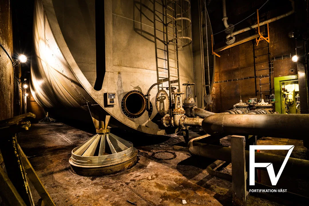
Supported useThis is an incremental fuel-storage component beside the F 9 Säve rock hangar. A steep stair enters a horseshoe-shaped shock-wave tunnel. Two sequential shock doors lie on either side of an approximately 2.5 m thick wall, followed by another roughly 60 steps and long exposed-rock passages. A third shock door protects the smaller tank space. The two tanks hold 500 and 700 m³, 1,200 m³ total; the larger sits in a side chamber behind the smaller. The original fixed in-hangar refuelling scheme was abandoned because ventilation was inadequate around fuel and ammunition, so 2.5 m³ rolling tanks and mobile PUG pumps were used. A separate fixed apron system/pump station was prepared but never completed. No cavern area, excavation volume, passage cross-section or construction cost is given.
Geometry evidenceportals: count: 1 | scope: observed surface/descent access system | evidence: One grating/door and steep stair into the horseshoe shock tunnel are described. | caution: The article says there was originally only one descent from the eastern hangar ramp, but does not establish the present total number of independent external accesses. | inner_structure: Two rock tank chambers/side spaces connected by long exposed-rock passages and protected by concrete blast barriers.; Approximately 2.5 m thick wall between two sequential shock doors. | other: Tank 1 capacity: 500 m³.; Tank 2 capacity: 700 m³.; Total storage capacity: 1,200 m³.; Rolling refuelling tanks: 2.5 m³ each.; Approximately 60 stair steps after the first blast barrier; step count is not a vertical height.; Three internal shock-wave doors are described in total.
Systems describedTwo bulk aviation-fuel tanks with pipelines and removable filters.; Protected horseshoe entrance, sequential shock doors and heavy barrier wall.; Mobile two-stroke PUG pumping/filtering units and 2.5 m³ rolling tanks.; Fixed electrical/fuel connections at hangar servicing positions.; Prepared but unfinished fixed pipes and pump station serving the southern apron/airfield.; Ventilation was insufficient for in-hangar refuelling, creating an explosion concern.
Primary cost driversTank-chamber and access-passage excavation/support.; Two 500/700 m³ tanks and hazardous fuel-transfer process.; Blast-barrier wall and three internal protective doors.; Explosion-safe ventilation, fire suppression, leak detection and containment.; Pumps, filtration, piping and apron/hangar transfer interfaces.; Access stairs and protected utilities.
Unit / programme scopeOne incremental 1,200 m³ fuel facility. The F10 consumption example of 100 m³/day is a comparator, not F9 consumption. Never add the child blindly to an inclusive F 9 hangar total.
Revision directionHeld after source-specific review.
Missing inputsTank dimensions and chamber plan/section.; Access-passage lengths/cross-sections and total excavation.; Containment slab/wall quantities and drainage.; Current hazardous-area ventilation, fire, gas/leak detection and separation criteria.; Piping/pump/filter inventory and transfer duty.; Clarification whether the unfinished fixed apron system is included in functional replacement.; Allocation/double-count boundary with the parent hangar.
Site / data issuesThe current 800 m² / 8,611 ft² floor-area and derived cavern/concrete quantities are assumptions.; Two sequential doors around a 2.5 m wall plus a third internal door are protective barriers, not three external portals.; The fixed apron refuelling system was never completed; including it changes the functional scope.; The child must not be summed with an inclusive parent-hangar estimate without checking the parent's boundary.